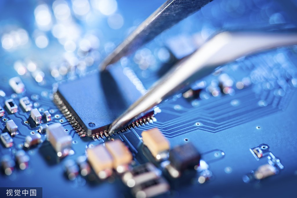
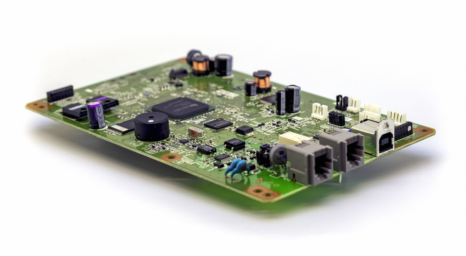
Soldering wires to a PCB board is a fundamental skill in electronics manufacturing and repair. This process is essential in pcba manufacturing and ensures reliable electrical connections. Whether you are a seasoned technician or a beginner, mastering the art of soldering wires to a PCB is crucial for ensuring the durability and functionality of your electronic assemblies.
Understanding the Basics
Tools and Materials Required
Before you begin, gather the necessary tools and materials. These include:
1. Soldering iron and solder
2. Wire stripper
3. Soldering flux
4. Helping hands or a vice
5. Desoldering pump or braid (for corrections)
6. Heat shrink tubing (optional for insulation)
7. Safety equipment (gloves and goggles)
Preparing the PCB and Wires
Proper preparation is key to achieving a strong solder joint. Start by ensuring that both the PCB and the wires are clean and free from oxidation. This can be done using isopropyl alcohol and a lint-free cloth. Next, tin the soldering iron tip by melting a small amount of solder onto it, which will help in efficient heat transfer.
Step-by-Step Soldering Process
Step 1: Strip the Wire
Use a wire stripper to remove a small section of the insulation from the end of the wire, exposing about 3-5mm of the conductor. Be careful not to nick the wire strands, as this can weaken the connection.
Step 2: Tin the Wire
Apply a small amount of solder to the exposed wire strands. This process, known as “tinning,” helps in creating a more stable and easy-to-solder connection. Simply touch the soldering iron to the wire and feed a small amount of solder until it covers the strands evenly.
Step 3: Position the Wire
Insert the tinned wire through the appropriate hole on the PCB. If you’re working with a pcb cable assembly, ensure that the wire placement aligns with the circuit design. Use helping hands or a vice to hold the PCB steady during this process.
Step 4: Apply Solder
Heat the joint by placing the soldering iron tip against both the wire and the PCB pad. Once the joint is heated, feed solder into the connection, allowing it to flow and cover the pad and wire evenly. Avoid using too much solder, as this can create bridges to adjacent pads and cause shorts.
Step 5: Inspect the Joint
A good solder joint should appear shiny and smooth, with a concave shape around the wire and pad. If the joint is dull or has gaps, it may be a cold solder joint and should be reheated and re-soldered. For pcba manufacture, ensuring each connection is flawless is critical to the board’s performance.
Step 6: Clean the Joint
Remove any flux residue with isopropyl alcohol and a brush. This is particularly important in professional pcba factory settings, where cleanliness can impact the reliability of the board. Inspect the joint under a magnifying glass to confirm its integrity.
Additional Tips for Quality Soldering
Use Flux
Flux is essential for preventing oxidation during the soldering process and ensuring a strong bond between the wire and the PCB. Applying a small amount of flux to the joint area can significantly improve the quality of the solder joint.
Maintain Proper Temperature
Soldering iron temperature should be appropriately set, usually between 350-400°C (662-752°F), depending on the solder type. Using a temperature-controlled soldering station can help maintain consistent heat, which is crucial for high-quality solder joints.
Practice Safety
Always prioritize safety by wearing protective gear and working in a well-ventilated area. Avoid inhaling solder fumes and ensure that the soldering iron is placed in a secure stand when not in use.
Conclusion
Soldering wires to a PCB is a fundamental skill that requires practice and attention to detail. By following these steps, you can achieve reliable and durable connections essential for any electronic project, from simple repairs to complex turnkey pcb assembly services. At ArisenTec, we emphasize precision and quality in all aspects of pcba manufacturing, ensuring that our products meet the highest industry standards.
For more information on our services and products, visit ArisenTec.
Choosing the Right Wires for Breadboard Wiring: A Comprehensive Guide
Breadboards are a staple in electronic circuit building, offering flexibility and ease of use for both beginners and professionals. However, one of the most critical aspects of working with breadboards is selecting the right wires. The wires you choose can impact not only the functionality of your circuit but also its longevity and ease of…
How to Improve Heat Dissipation in PCB Design
Introduction As modern electronic devices become more complex and power-dense, heat dissipation has emerged as a critical factor that directly impacts device performance and reliability. Excessive junction temperatures in electronic systems can shorten the lifespan of components and lead to system failure. Thus, optimizing the PCB (Printed Circuit Board) design to improve heat dissipation is…
Manufacturing Process of Multilayer PCBs
Multilayer PCB manufacturing methods include the plated-through hole (PTH) and high-density interconnect (HDI) methods, both achieved by combining different processes to realize the circuit board structure. Currently, the most widely used method is the PTH method, which has been developed and refined over more than half a century. The PTH method is mature in terms…


