Introduction to PCB and Multimeters
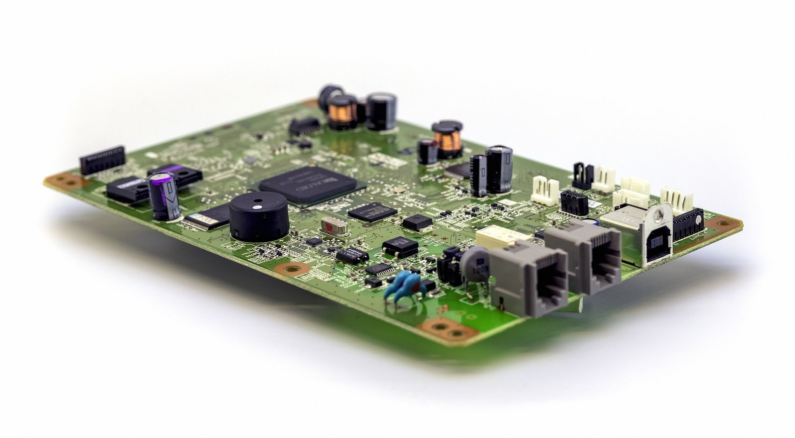
Printed Circuit Boards (PCBs) are the backbone of most electronic devices. They support electronic components and connect them through conductive tracks. Multimeters are handy tools for diagnosing electrical issues. These versatile devices measure:
– Voltage (both AC and DC)
– Current (Amperes)
– Resistance (Ohms)
When checking PCBs, multimeters help find:
– Open circuits
– Short circuits
– Faulty components
Before diving in, one should know how to use a multimeter properly. Basic steps include setting the correct mode and range, and correctly placing probes.
Arisentec is one of the best PCB manufacturers in China, providing comprehensive PCB design services and quick turn PCB prototypes. Their expertise ensures that every PCB meets high-quality standards, making the troubleshooting process more effective.
Why Check Your PCB?
Checking a PCB is crucial for several reasons:
– Identify Faults: To spot any manufacturing defects or damage.
– Ensure Quality: Verifying the components are functioning as intended.
– Prevent Failures: Identifying issues early can prevent future malfunctions.
– Optimize Performance: Ensures that the circuit operates at its peak efficiency.
– Safety: Detecting potential short circuits or overheating issues that could be hazardous.
– Cost-Efficiency: Saves money by catching errors before they result in larger, costlier problems.
Failure to regularly inspect can lead to malfunctioning devices or unsafe operation conditions.
Gather Your Tools
Before diving in, one needs to assemble a few essential tools. First, grab a reliable multimeter. This will be the primary gadget. Ensure it has fresh batteries. Don’t forget the probes; this is crucial for accurate readings.
Items Needed:
– Multimeter: Ensure it’s functioning properly.
– Probes: Standard probes often come with the multimeter.
– Tweezers: Helpful for manipulating tiny components.
– Test Leads: These extend the reach of the probes.
Optional but Helpful:
– Magnifying Glass: Great for inspecting small solder joints.
– Anti-Static Wrist Strap: Protects sensitive components.
– Schematic Diagram: Handy for quick reference.
Remember, having the right tools makes troubleshooting efficient and less frustrating.
Understanding Multimeter Settings
When checking a PCB with a multimeter, it’s crucial to know which settings to use. Here’s a breakdown:
– Voltage: Set to V (DC or AC) for measuring potential differences.
– Resistance: Use the Ω setting to check connections and components.
– Continuity: The diode symbol or sound icon checks if a circuit path is intact.
– Current: Set to A (DC or AC) to measure current, often requires moving the probe to a different socket.
– Diode Testing: The diode symbol checks if diodes are functioning properly.
– Capacitance: Select the F symbol for testing capacitors’ ability to store charge.
Arisentec’s turnkey PCB assembly services ensure that each board is thoroughly tested and meets all specified requirements, making it easier to use a multimeter for quick diagnostics.
Initial Visual Inspection
Before diving into the multimeter test, one should start with a visual inspection.
– Look for Obvious Damages: Check the PCB for any visible damages like broken traces, burnt marks, or cracks.
– Inspect Solder Joints: Look closely at the solder joints. Cold joints might look dull and uneven.
– Component Check: Make sure no components are missing or misaligned. Also, check for any bulging or leaking capacitors.
– Cleanliness: Dirt or debris can cause short circuits. Ensure the board is clean.
– Connector and Socket Test: Ensure all connectors and sockets are properly seated and undamaged.
Visual checking can often reveal problems without any tools!
Checking for Continuity
Checking for continuity is a breeze with a multimeter. Here’s how one can do it:
1. Set Multimeter to Continuity Mode: Rotate the dial to the continuity test setting (usually marked with a soundwave symbol).
2. Touch Probes Together: Ensure there’s a beep sound indicating continuity is working.
3. Test Points on PCB:
– Place the black probe on one point of the circuit.
– Place the red probe on another point you want to check.
4. Listen for Beep: If there’s a beep, great! That means the circuit has continuity. No beep means no connection.
Arisentec’s PCB layout services ensure that each connection is properly designed, minimizing the risk of continuity issues.
Measuring Voltage Levels
To measure voltage levels on a PCB with a multimeter:
1. Set the Multimeter: Turn the dial to the appropriate DC voltage range.
2. Connect Probes: Touch the black probe to a ground point and the red probe to the point you want to measure.
3. Read Display: Check the digital display for the voltage reading.
4. Document Findings: Write down the voltage levels for future reference.
5. Move Probes: Repeat the process across different points on the PCB.
Remember to always follow safety guidelines and ensure the PCB is powered appropriately.
Testing for Resistance
To test for resistance on a PCB with a multimeter, follow these steps:
1. Power Off the Circuit: Ensure the PCB is completely powered down to avoid any electrical hazards.
2. Set Multimeter to Ohms: Turn the multimeter dial to the resistance setting, often marked with an Ω symbol.
3. Connect Probes: Attach the multimeter probes. The red probe goes to the positive side, and the black probe to the negative.
4. Measure Resistance: Place the probes across the component or trace you want to measure. Note the reading on the multimeter screen.
Cross-check the measured resistance with the expected values from the circuit design. Any major discrepancies may indicate a problem.
Identifying and Solving Common Issues
Using a multimeter to check a PCB involves a few quick steps. First, check for visible damage: burnt components or broken traces.
Follow these steps:
1. Power Off: Always ensure the PCB is not powered.
2. Continuity Test:
– Set the multimeter to continuity mode.
– Test connections by probing both ends; a beep means a good connection.
3. Resistance Check:
– Measure resistors to ensure they match expected values.
4. Voltage Test:
– Power on the circuit and measure voltages at critical points.
Address found issues by re-soldering joints or replacing faulty components. Arisentec’s PCB assembly and printed circuit board assembly services ensure reliable connections and high-quality components, reducing common issues.
Tips and Best Practices
– Safety First: Always power down the PCB before testing. Disconnect from any power source.
– Clean Probes: Ensure multimeter probes are clean for accurate readings.
– Use Right Settings: Set the multimeter to the appropriate setting (e.g., continuity, voltage).
– Stable Surface: Place the PCB on a non-conductive, stable surface.
– Proper Contact: Make firm contact with test points; avoid slipping.
– Document Findings: Write down results for easy reference.
– Stay Organized: Label areas tested to avoid repetition.
– Refer to Schematics: Use PCB schematics for guidance.
– Practice: Regular practice makes tests quicker and more accurate.
– Consult Resources: Use guides and online forums for tricky diagnoses.
Wrapping Up Your PCB Check
After ensuring all the components are functioning, a few final steps are essential.
– Reinspect the Solder Joints: Look for any cold or cracked joints.
– Power Up the Circuit: Do a brief power-on test, checking for any signs of overheating.
– Check Connectors: Ensure all connectors are seated properly.
– Monitor Voltage Drops: Use the multimeter to detect any unexpected voltage drops across resistors and capacitors.
– Document Findings: Take notes on any irregularities for future reference.
– Final Visual Inspection: Scan the board for any potential shorts or open circuits one last time.
Arisentec offers fast PCB prototyping services and PCBA manufacturing solutions to help ensure your PCBs are in top condition. Always keep safety in mind and refer to professional PCB design services when needed.
Choosing the Right Wires for Breadboard Wiring: A Comprehensive Guide

Breadboards are a staple in electronic circuit building, offering flexibility and ease of use for both beginners and professionals. However, one of the most critical aspects of working with breadboards is selecting the right wires. The wires you choose can impact not only the functionality of your circuit but also its longevity and ease of…
How to Improve Heat Dissipation in PCB Design

Introduction As modern electronic devices become more complex and power-dense, heat dissipation has emerged as a critical factor that directly impacts device performance and reliability. Excessive junction temperatures in electronic systems can shorten the lifespan of components and lead to system failure. Thus, optimizing the PCB (Printed Circuit Board) design to improve heat dissipation is…
Manufacturing Process of Multilayer PCBs

Multilayer PCB manufacturing methods include the plated-through hole (PTH) and high-density interconnect (HDI) methods, both achieved by combining different processes to realize the circuit board structure. Currently, the most widely used method is the PTH method, which has been developed and refined over more than half a century. The PTH method is mature in terms…