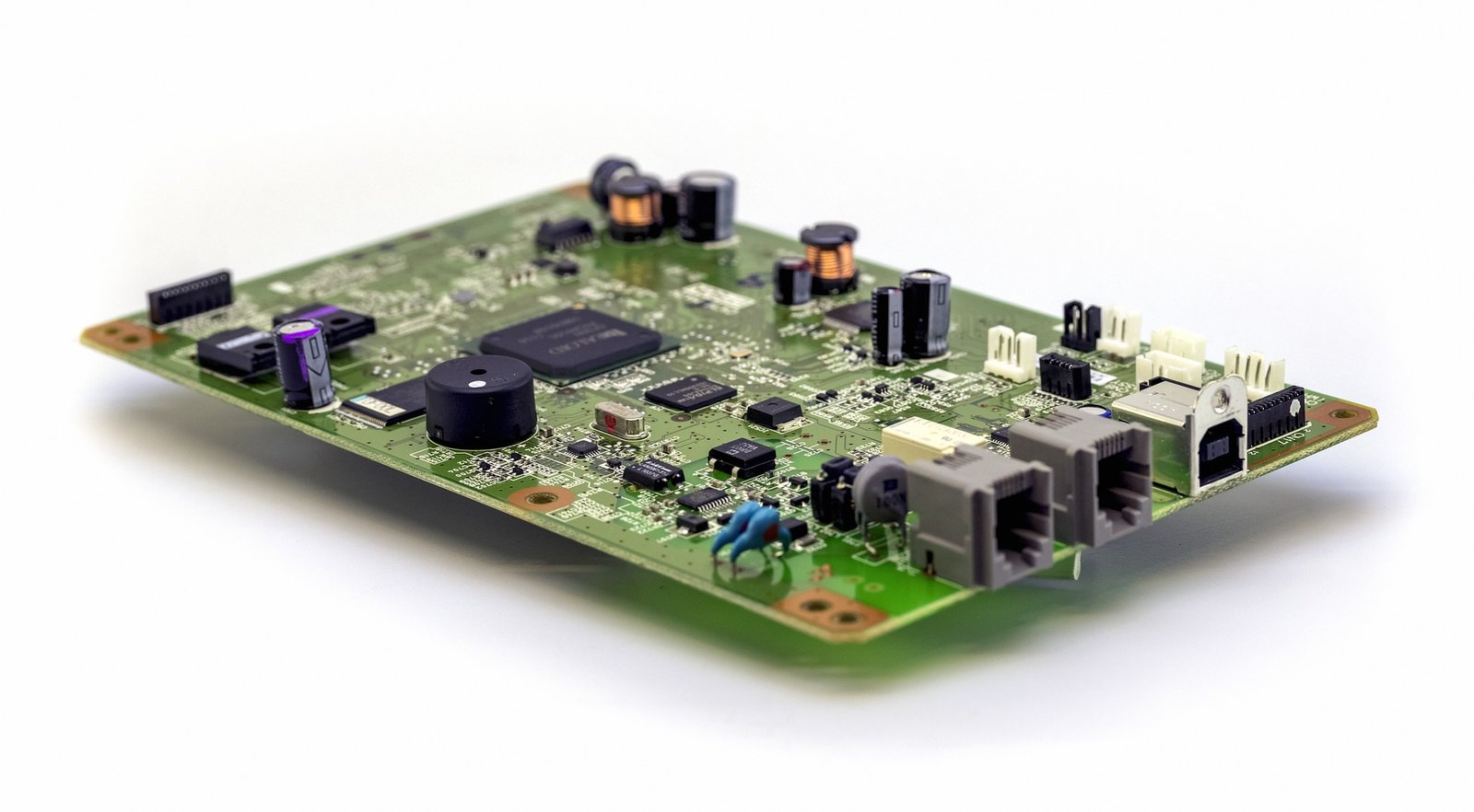
Testing a Printed Circuit Board (PCB) is a critical step in ensuring the functionality and reliability of electronic devices. A multimeter is one of the most versatile tools used for this purpose. It allows technicians and engineers to check various parameters, including continuity, resistance, voltage, and current, to diagnose issues and verify that the PCB is functioning as intended.
1. Preparing for the Test
Before beginning the testing process, it is essential to prepare both the PCB and the multimeter:
Safety First
Ensure that the PCB is powered off before testing to avoid damaging the board or the multimeter. If the board has capacitors, discharge them to prevent any residual voltage from affecting the readings or causing harm.
Selecting the Correct Multimeter Settings
A digital multimeter is preferred for its accuracy and ease of use. Depending on the tests to be conducted, set the multimeter to the appropriate mode:
· Continuity Testing: Set the multimeter to continuity mode, often indicated by a soundwave symbol.
· Resistance Measurement: Set the multimeter to resistance mode, denoted by the “Ω” symbol.
· Voltage Measurement: Set the multimeter to the appropriate DC voltage range if checking power supplies or signal paths.
2. Continuity Testing
Purpose
Continuity testing is used to ensure that there are no breaks in the electrical paths on the PCB. This test confirms that connections between components and traces are intact.
Procedure
1. Place the Probes: Place the black probe on one end of the circuit (e.g., a solder joint or a pin) and the red probe on the other end.
2. Check the Reading: The multimeter will emit a beep if there is continuity. If the multimeter shows no reading or beeps, there may be a broken trace or a faulty connection.
3. Test Multiple Points: Test different sections of the PCB to ensure complete continuity throughout the board.
3. Resistance Measurement
Purpose
Measuring resistance helps in identifying issues like shorts, incorrect component placement, or damaged components on the PCB.
Procedure
1. Set the Multimeter to Resistance Mode: Select the appropriate resistance range.
2. Place the Probes: Connect the multimeter probes across the component or section of the circuit where you want to measure resistance.
3. Interpret the Results: Compare the resistance value with the expected value provided in the circuit design or component specifications. Significant deviations may indicate a problem.
4. Voltage Testing
Purpose
Voltage testing verifies that the correct voltages are present at various points on the PCB, which is crucial for the proper functioning of the circuit.
Procedure
1. Power On the PCB: Carefully power on the PCB and ensure it is operating under normal conditions.
2. Set the Multimeter to DC Voltage Mode: Choose the appropriate voltage range for your circuit.
3. Test Key Points: Measure the voltage across key components such as power supply lines, IC pins, and connectors.
4. Compare with Design Specifications: Verify that the measured voltages match the expected values listed in the circuit design documentation.
5. Troubleshooting Common Issues
Short Circuits
Short circuits are a common problem in PCBs, often caused by solder bridges or damaged components. To detect a short circuit, use the continuity mode. If continuity is detected between two points that should not be connected, you likely have a short circuit.
Open Circuits
Open circuits occur when a connection that should be present is missing, often due to a broken trace or a cold solder joint. Continuity testing can help identify open circuits by revealing where the electrical path is interrupted.
Incorrect Component Values
If the PCB is not functioning correctly, it might be due to components with incorrect values or faulty components. Measure resistance, capacitance, or diode functionality using the multimeter to ensure that each component matches its specified value.
6. Final Checks and Reassembly
After testing and troubleshooting, perform a final round of checks to ensure all issues have been addressed. Verify that there are no short circuits, all components are functioning correctly, and the voltages are within the expected range. Once satisfied with the results, carefully reassemble the PCB into its housing or device.
Conclusion
Using a multimeter to test a PCB is an essential skill for anyone involved in electronics manufacturing or repair. It ensures that the PCB meets the required specifications and helps in identifying and fixing issues early in the manufacturing process. Properly testing with a multimeter can significantly reduce the printed circuit board cost by minimizing the need for rework and ensuring that the final product is of the highest quality. Whether dealing with pcba manufacturing or conducting a pcb prototyping service, mastering this process is crucial for maintaining high standards in PCB production.
Choosing the Right Wires for Breadboard Wiring: A Comprehensive Guide
Breadboards are a staple in electronic circuit building, offering flexibility and ease of use for both beginners and professionals. However, one of the most critical aspects of working with breadboards is selecting the right wires. The wires you choose can impact not only the functionality of your circuit but also its longevity and ease of…
How to Improve Heat Dissipation in PCB Design
Introduction As modern electronic devices become more complex and power-dense, heat dissipation has emerged as a critical factor that directly impacts device performance and reliability. Excessive junction temperatures in electronic systems can shorten the lifespan of components and lead to system failure. Thus, optimizing the PCB (Printed Circuit Board) design to improve heat dissipation is…
Manufacturing Process of Multilayer PCBs
Multilayer PCB manufacturing methods include the plated-through hole (PTH) and high-density interconnect (HDI) methods, both achieved by combining different processes to realize the circuit board structure. Currently, the most widely used method is the PTH method, which has been developed and refined over more than half a century. The PTH method is mature in terms…


