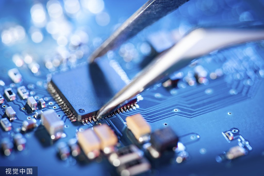
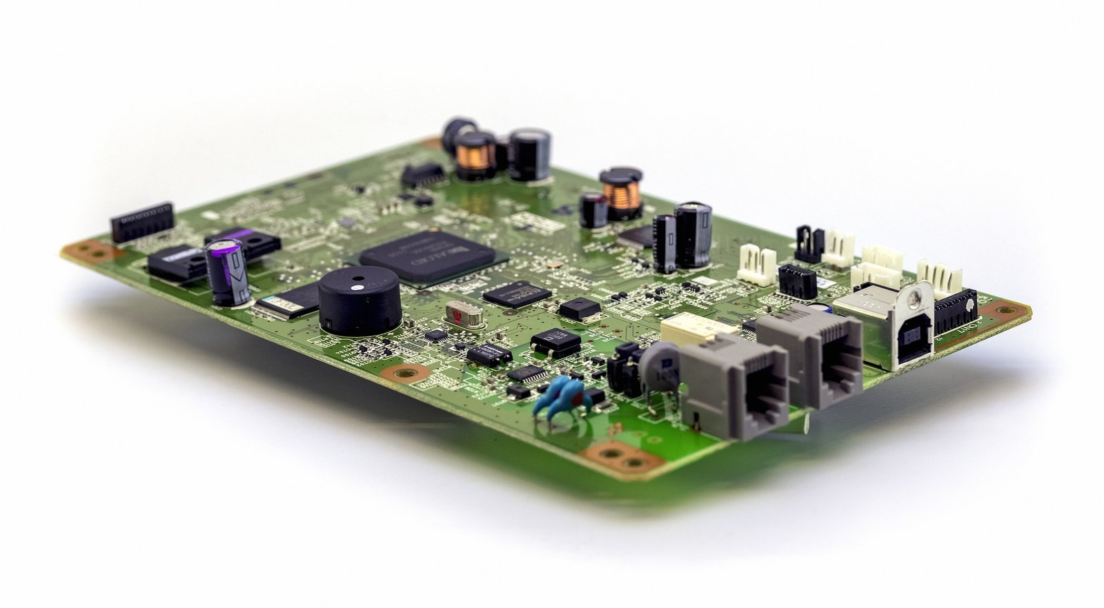
Programming a printed circuit board (PCB) involves loading firmware or software onto a microcontroller or processor embedded within the PCB. This process is crucial for enabling the PCB to perform its intended functions, such as controlling devices, processing data, or managing communication. Below is a guide on how to program a PCB, with insights into how ArisenTec can support your PCB programming needs.
1. Understanding the PCB and Microcontroller
Before programming a PCB, it’s essential to understand the specific microcontroller or processor used on the board. This involves knowing its architecture, supported programming languages, and available development tools. ArisenTec’s expertise in pcba manufacturing ensures that each PCB is designed with the appropriate microcontroller, tailored to meet specific project requirements.
2. Setting Up the Development Environment
The first step in programming a PCB is to set up a suitable development environment. This typically includes:
· Integrated Development Environment (IDE): Software like Arduino IDE, MPLAB X, or Atmel Studio tailored for specific microcontrollers.
· Compiler/Assembler: Converts your code into machine language that the microcontroller can execute.
· Programmer or Debugger: Hardware tools such as USB programmers or in-circuit debuggers (ICD) are used to transfer the compiled code onto the PCB.
ArisenTec provides comprehensive support in setting up and optimizing your development environment, ensuring seamless integration with our custom-designed PCBs.
3. Writing the Firmware
Firmware development involves writing code that will run on the microcontroller. This is usually done in languages like C, C++, or assembly. Key steps include:
· Initialization: Setting up the microcontroller’s registers, I/O pins, and peripherals.
· Main Loop: Writing the primary function or loop where the microcontroller continuously monitors inputs and controls outputs.
· Interrupt Service Routines (ISRs): Code that handles specific events like timers or input changes, ensuring the microcontroller responds quickly to these events.
ArisenTec’s team of experts can assist in developing firmware that is optimized for performance and reliability, enhancing the overall functionality of your PCB.
4. Compiling and Debugging
Once the code is written, it must be compiled into a format that the microcontroller can understand, typically a .hex or .bin file. This compiled code is then loaded onto the microcontroller using a programmer. Debugging is an iterative process where you run the code, monitor outputs, and correct any issues.
· Simulation Tools: Many IDEs offer simulation tools to test the code before actual programming.
· On-Board Testing: Once the firmware is loaded onto the PCB, it’s essential to test it under real-world conditions, ensuring that all components operate correctly.
ArisenTec ensures that all compiled code is rigorously tested to meet the highest industry standards, minimizing errors and ensuring a smooth programming process.
5. Programming the PCB
With the code ready, the next step is to program the PCB:
· Connect the Programmer: Attach the programmer to the PCB via a programming header or a standard interface like JTAG or SPI.
· Load the Firmware: Use the IDE or a dedicated programming tool to load the compiled firmware onto the microcontroller.
· Verify the Programming: After programming, many tools offer a verification process to ensure the code was correctly loaded and is running as expected.
ArisenTec provides turnkey solutions that include not only PCB design and assembly but also programming and verification, ensuring that your project is ready for deployment.
6. Testing and Validation
After programming, the PCB should undergo thorough testing to validate its functionality. This includes:
· Functional Testing: Ensuring that all inputs and outputs behave as expected.
· Stress Testing: Operating the PCB under various conditions to test its reliability.
· Compliance Testing: Verifying that the PCB meets industry standards, such as EMC compliance for electronic devices.
ArisenTec’s turnkey PCB assembly services include extensive testing and validation, ensuring that each PCB meets the highest quality standards and is ready for its intended application.
7. Final Considerations
Programming a PCB is a critical part of the pcba manufacturing process, especially for turnkey PCB assembly services where the entire design, assembly, and programming are handled by a single provider. The success of the programming phase directly impacts the printed circuit board cost, as errors in this stage can lead to rework or even redesigns.
With ArisenTec’s expertise and commitment to quality, you can be confident that your programmed PCB will function correctly in its intended application, whether in automotive PCB service, smart home PCB, or other specialized industries. Visit ArisenTec PCB to learn more about how we can support your next project.
Choosing the Right Wires for Breadboard Wiring: A Comprehensive Guide
Breadboards are a staple in electronic circuit building, offering flexibility and ease of use for both beginners and professionals. However, one of the most critical aspects of working with breadboards is selecting the right wires. The wires you choose can impact not only the functionality of your circuit but also its longevity and ease of…
How to Improve Heat Dissipation in PCB Design
Introduction As modern electronic devices become more complex and power-dense, heat dissipation has emerged as a critical factor that directly impacts device performance and reliability. Excessive junction temperatures in electronic systems can shorten the lifespan of components and lead to system failure. Thus, optimizing the PCB (Printed Circuit Board) design to improve heat dissipation is…
Manufacturing Process of Multilayer PCBs
Multilayer PCB manufacturing methods include the plated-through hole (PTH) and high-density interconnect (HDI) methods, both achieved by combining different processes to realize the circuit board structure. Currently, the most widely used method is the PTH method, which has been developed and refined over more than half a century. The PTH method is mature in terms…


